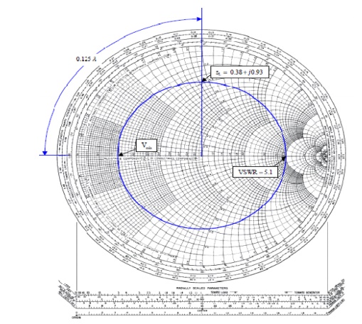
Smith Chart is a convenient graphical means of determining voltages along transmission lines. (a) Using Convolution, find output y for input x = 8(n] + 28 +Ĩ and h(n] = U(n]. Voltage and Current Waves in general transmission lines. Let the discrete system is defined by input x, output y and system (c) Decide its frequency response H(elo).

(b) Is this system stable? give reasoning for your answer. (a) Decide its system impulse response h(n). The location of voltage minimum is on the left because. The location of voltage minimum is on Question: QUESTION 23 Which of the followings is true On Smith chart O A. The location of voltage minimum is on the left because the admittance is minimum. Compute the DC Bias (only IE).ĭraw the small signal model and find the overall voltage gains (vo/vsig). The location of voltage minimum is on the left because the impedance is minimum. Use the attached Smith Chart to find:(a)(2 points) The magnitude I and phase A of the reflection coefficient. Consider the lossless transmission line given below. (50 points) This problem has 14 questions.Find the input impedance Rin as indicated in the figure.įind the output impedance Rout as indicated in the figure. The circuit parameters are VDD=5V, Rs=1KΩ, RD= 4KΩ, R1=225KΩ, and R2=175KΩ.įind the circuit quiescent values IDQ and VDSQ.įindthesmallsignalvoltagegainforRLasanopencircuit.

An NMOS common-source amplifier circuit shown as the figure, the transistor parameters are: VTN=0.8V, Kn = 1mA/V2, and the channel modulation effect is ignored.

Smith chart voltage minimum how to#


 0 kommentar(er)
